English
 Türkçe

No matter how high the power of an electric motor is, that power is useless if it cannot reach the shaft. The shaft is the bridge that transfers the rotary motion and torque the motor produces to the outside world, that is, to the load. The smoothness of this transfer depends on the shaft diameter, the keyway connection, and the coupling being selected in accordance with the correct dimensions and standards. A wrong shaft diameter or an incompatible coupling causes vibration, wear, and efficiency loss from the very first day. At DRG Motor, we design the shaft connection dimensions of the AC induction motors we supply in accordance with international standards; thus our motors work seamlessly with the connection elements common in the field. In this article we address in detail the relationship of shaft diameter with frame size, keyway dimension standards, shaft end features, and coupling types along the axis of dimensions and standards. This article is dimension- and standard-focused; shaft alignment is a separate and complementary topic.
The Role of the Shaft Inside the Motor
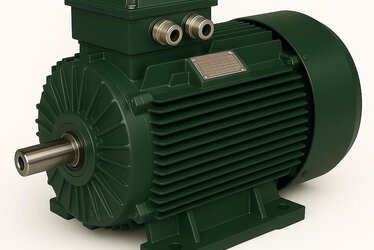
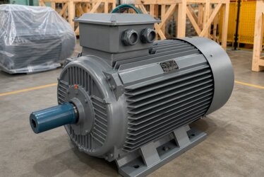
The shaft is a steel axis that passes through the center of the rotor and carries the rotary motion outward. All the torque the motor produces is transmitted through this shaft. For this reason, the shaft must be both strong enough to withstand high torque and precisely machined enough to rotate without vibration.
One end of the shaft is connected to the rotor inside the motor, while the other end extends outward and connects to the load. This protruding end is called the "shaft end," and connection elements such as couplings, pulleys, or gears are attached to this end. Correct sizing of the shaft is the foundation of the entire power transmission chain.

The Relationship Between Shaft Diameter and Frame Size
In electric motors, the shaft diameter is not determined randomly; it is directly related to the frame size. International IEC standards define a specific shaft diameter for each frame size. Thanks to this standardization, motors of different suppliers with the same frame size have the same connection dimensions and can be used interchangeably.
As the frame size grows, so does the shaft diameter. The reason for this is clear: larger-frame motors produce higher power and torque, which means the load on the shaft increases. The shaft diameter is enlarged to safely carry this increasing torque. This relationship between frame size and shaft diameter is one of the fundamental criteria of motor selection.
The Compatibility Standardization Provides
The standardization of shaft diameter is a great advantage for facilities. When a motor fails and needs to be replaced, since the new motor of the same frame size will have the same shaft diameter, the existing coupling, pulley, and connection elements can be used directly. This saves both time and cost.
Standardization also makes spare parts management easier. The facility can keep standard coupling and key dimensions in stock in advance according to frame size. In industrial applications, this compatibility means rapid intervention and low downtime; in this regard, our industrial electric motors article provides useful information.
The Function of the Keyway Connection
One of the most important details on the shaft end is the keyway. The key is a small but critical connection element that transmits the rotary torque between the shaft and the coupling or pulley mounted on it. The key, placed into the keyway cut on the shaft end, keeps the connection element fixed on the shaft without rotating or slipping.
Without a key, the coupling or pulley can rotate freely on the shaft and slip, and the torque cannot be transmitted. For this reason, the key connection is a fundamental mechanical lock that ensures the safety of power transmission. Correct sizing of the key is directly proportional to the torque it will transmit.
Keyway Dimension Standards
Key dimensions, like the shaft diameter, are standardized. A specific key width and height are defined for each shaft diameter. Thanks to these standards, the key and keyway dimensions suitable for a shaft diameter are known in advance, and connection elements are produced accordingly.
The key is usually a steel piece with a rectangular cross-section, and its width, height, and slot depth have standard values according to the shaft diameter. The key dimension being suitable for the shaft diameter is mandatory for the torque to be transmitted safely. A key that is too small can be sheared at high torque; for this reason, the key dimension should always be selected in accordance with its standard for the shaft diameter.

Approximate Shaft Diameter Table by Frame Size
The table below shows the standard shaft diameters corresponding to common frame sizes and the approximate key widths suitable for these diameters. These values are typical correspondences for standard designs; exact values should be verified from the motor's nameplate and technical documentation.
| Frame Size | Approx. Shaft Diameter | Approx. Key Width |
|---|---|---|
| 80 | 19 mm | 6 mm |
| 90 | 24 mm | 8 mm |
| 100-112 | 28 mm | 8 mm |
| 132 | 38 mm | 10 mm |
| 160 | 42 mm | 12 mm |
| 180 | 48 mm | 14 mm |
| 200 | 55 mm | 16 mm |
| 225 | 60 mm | 18 mm |
| 250-280 | 65-75 mm | 18-20 mm |
As can be seen from the table, as the frame size grows, both the shaft diameter and the key width increase. This increase ensures that the rising torque is transmitted safely.
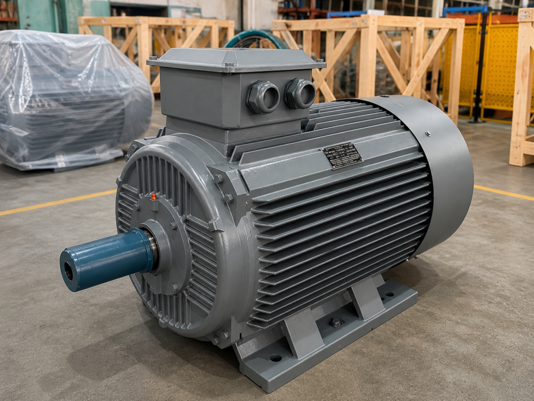
Shaft End Features and Tolerances
The shaft end is not just a diameter; its length, surface quality, and tolerance are also determined by standards. The length of the shaft end is designed to be sufficient for the coupling or pulley to be mounted on it to seat fully. If the surface is too rough, the connection element does not seat fully; if it is too slippery, the risk of slipping increases.
The tolerance of the shaft end diameter is also critical. If the connection element sits too loosely on the shaft, a gap forms and vibration begins; if it sits too tightly, assembly becomes difficult and the shaft may be damaged. Standard tolerances provide an ideal tightness between these two extremes. For this reason, the shaft end is a region that requires precise machining.
What Is a Coupling and Why Is It Needed
A coupling is a mechanical connection element that connects the motor shaft to the load's shaft (for example, the shaft of a pump or gearbox). Without a coupling, directly connecting the motor and the load is not possible in most applications; because there are, however small, alignment differences, axial movements, and vibrations between the two shafts.
The coupling transmits the torque safely by tolerating these differences to a certain extent. It also provides the ability to easily separate the motor from the load during assembly and maintenance. Correct coupling selection determines both the efficiency of power transmission and the life of the connection.
Flexible Couplings
Flexible couplings are a coupling type that can dampen small alignment differences and vibrations between the motor and load shaft. They usually contain an elastic intermediate element (rubber or flexible material). This element tolerates angular, parallel, and axial misalignments between the two shafts within certain limits.
Flexible couplings are the most commonly used coupling type in industry because they reduce vibration and increase assembly tolerance. However, the flexible coupling providing tolerance does not mean that alignment is unimportant; correct alignment is still required to stay within the coupling's tolerance limits. How to perform alignment is a separate topic and is addressed in detail in our motor shaft and coupling alignment article.

Rigid Couplings
Rigid couplings are a coupling type that fix two shafts to each other almost as a single shaft. They provide no flexibility or tolerance; for this reason, they are used only in applications where the two shafts can be aligned very precisely. Even the smallest alignment error in a rigid coupling loads directly onto the bearings.
The advantage of rigid couplings is that they transmit high torque without play and one-to-one. For this reason, they are preferred in applications that require precise positioning and where alignment can be ensured very well. In rigid coupling use, alignment precision is far more critical than in a flexible coupling.
Torque and Speed in Coupling Selection
Coupling selection is made not only according to the shaft diameter but also according to the torque to be transmitted and the operating speed. The coupling must have the capacity to safely carry the maximum torque the motor produces and especially the high torque at the initial start. A coupling of insufficient capacity can wear or break at high torque.
In high-speed applications, it is also important that the coupling be balanced; an unbalanced coupling produces vibration. For this reason, when selecting a coupling, both the torque capacity and the operating speed should be evaluated together. Our motor gearbox compatibility article provides complementary information on selecting the motor to suit the load.
Shaft Load: Radial and Axial Forces
Not only rotary torque but also radial (perpendicular to the shaft) and axial (along the shaft direction) forces act on the shaft. While a belt-pulley connection loads high radial load on the shaft, some pump applications create axial load. These forces directly affect the life of the shaft and bearings.
The shaft and bearing should be selected to safely carry the expected radial and axial load. Excessive radial load causes bending at the shaft end and early wear in the bearings. For this reason, when selecting the connection type, the resulting shaft load must definitely be taken into account.
The Effect of Pulley and Belt Connection on the Shaft
In some applications, the motor is connected to the load with a belt-pulley instead of a coupling. This connection type requires special attention because it loads high radial load on the shaft. The pulley diameter, belt tension, and the position of the pulley on the shaft end directly affect the radial force on the shaft.
The pulley should be mounted as close to the shaft end (close to the bearing) as possible; because a radial load applied far from the shaft end creates a larger bending moment on the shaft. The correct pulley size and position are the key to protecting the shaft and bearing life. Our electric motor bearing types and selection article will be useful on bearing selection and life.
Shaft Material and Strength
The torque the shaft can carry depends not only on its diameter but also on the strength of the steel material it is produced from. Electric motor shafts are produced from steel of a quality that will withstand fatigue under high torque and variable load. The shaft surface is precisely machined in the regions where the coupling and bearings seat, and hardened when necessary.
A low-quality or incorrectly machined shaft can develop fatigue cracks over time and lead to a sudden fracture. For this reason, the quality of the shaft material is an invisible but fundamental component of the motor's reliability. At DRG Motor, we supply our shafts from steel that will safely withstand the expected torque and load conditions.
Double Shaft End Motors
In some applications, the motor has a shaft end at both of its ends; these are called double shaft end motors. This design allows the motor to drive two different loads at the same time or a feedback element such as an encoder to be connected to one end. In double shaft end motors, the dimensions and standards of both shaft ends should be considered separately.
The diameter of the second shaft end usually conforms to the same standard as the main shaft end, but in some designs it may be different. When selecting a double shaft end motor, the dimensions of the connection elements to be connected to both ends should be clarified from the start.
Assembly of the Shaft and Connection Elements
The assembly of the coupling or pulley onto the shaft is an operation that requires care. The connection element should not be forced onto the shaft by impact (with a hammer); because impact damages the shaft and bearings. The correct method is to expand the connection element by controlled heating when necessary and to place it properly onto the shaft.
During assembly, it should be ensured that the key seats fully into its slot and that the connection element advances up to the shaft shoulder. Wrong assembly both shortens the life of the connection and lays the groundwork for vibration and alignment problems.
Shaft End Threaded Hole and Fixing
Many motors have a threaded hole in the center of the shaft end. This hole is used to fix the coupling or pulley axially on the shaft. After the connection element is mounted on the shaft, with the help of a bolt and washer inserted into this threaded hole, the element is prevented from slipping off the shaft end.
This simple but important detail increases the safety of the connection, especially in applications that work under axial load or with vibration. Tightening this fixing bolt with the appropriate torque during assembly contributes to the long life of the connection.
Milling and Quality of the Keyway
The keyway on the shaft end is cut with a precise milling process. The width, depth, and corner radii of the slot must comply with the standard. Sharp transitions at the corners can cause stress concentration on the shaft and, over time, a fatigue crack; for this reason, the slot corners are rounded with an appropriate radius.
The quality of the keyway is critical for the torque to be transmitted smoothly. A defective or non-standard keyway causes the key to seat with play and an impact load to form during rotation. This results in early wear of both the key and the shaft end.
The Importance of Dimension and Standard Compatibility
The shaft diameter, key, and coupling being selected in accordance with standards is the foundation of the connection working trouble-free throughout its life. A non-standard shaft diameter or an incompatible key makes it difficult to find a suitable connection element in the field and requires custom production. This increases both cost and downtime.
A motor that conforms to standards, on the other hand, is directly compatible with the common coupling, pulley, and key dimensions in the field. This compatibility provides a great advantage in both ease of assembly and spare parts supply. Dimension and standard compatibility is a silent but decisive part of the motor's practical usability.
DRG Motor for Standard-Compliant Shaft and Connection
A motor's power turns into work only with a correctly sized shaft and a compatible connection element; the standard compliance of the shaft diameter, key, and coupling is the silent guarantee of power transmission. At DRG Motor, we design the shaft diameter, keyway, and shaft end dimensions of the AC induction motors we supply in accordance with international IEC standards; thus our motors work seamlessly with the connection elements common in the field. To select a motor with shaft and connection dimensions suitable for your application, you can review our DRG Motor products and get support from our technical team. A correctly sized shaft connection lays the foundation for years of vibration-free operation.