English
 Türkçe

A frequency inverter delivers energy to the motor while accelerating it; but when you want to decelerate the motor quickly, where does that energy go? This is exactly where dynamic braking and the brake resistor come into play. As the load slows down, the motor behaves for a moment like a generator and sends the energy it produces back to the inverter's DC bus. If this energy is left uncontrolled, the bus voltage rises to dangerous levels and the inverter trips. When driving DRG AC asynchronous motors with an inverter, setting up dynamic braking correctly, especially in crane, centrifuge, and high-inertia applications, is the key to both safety and performance. In this article we cover where the energy comes from, how the brake resistor works, and how to size it correctly.

What Happens During Braking?
When a motor is decelerated, the kinetic energy of the rotating mass must be dissipated somewhere. As the inverter lowers the motor's frequency, the rotor comes to turn faster than the magnetic field and the motor enters generator mode. In this mode mechanical energy is converted into electrical energy and flows toward the inverter.
The Source of Kinetic Energy
The amount of energy returning during deceleration depends on the inertia of the rotating mass and the change in speed. High-inertia loads such as a large flywheel, a heavy drum, or a high-speed centrifuge release a very serious amount of energy at the moment of stopping. Because this energy is released in just a few seconds, the instantaneous power can be very high.
Why Does the DC Bus Voltage Rise?
Inside the inverter, after the rectifier, there is a DC bus and a capacitor bank where energy is stored. When the motor enters generator mode, energy flows to this bus and charges the capacitors, raising the voltage. Since the capacitance is limited, the bus voltage exceeds the design limit if the returning energy is not absorbed quickly.
The Overvoltage Fault
When the DC bus voltage exceeds a certain threshold, the inverter trips with an overvoltage fault to protect itself and cuts the output. This leads to sudden stops on the production line, loss of position, and operational disruptions. The basic purpose of dynamic braking is to prevent this overvoltage fault.
What Is Dynamic Braking?
Dynamic braking is the method of dissipating the excess energy produced by the motor by converting it into heat across a resistor. A brake resistor connected to the inverter engages when the bus voltage rises, absorbing the energy and keeping the bus voltage within a safe range. The motor can thus be stopped as quickly as desired.
Brake Resistor and Chopper
The brake resistor does not work on its own; there is a semiconductor switch (brake chopper or brake transistor) that controls it. This chopper continuously monitors the DC bus voltage; when the voltage exceeds the threshold it connects the resistor to the bus, and when the voltage drops it disconnects it. This rapid on-off action keeps the bus voltage in a narrow band, providing controlled braking.

Where Does the Energy Go?
In dynamic braking the returning energy is not recovered; it is released to the atmosphere as heat. This is a simple and reliable solution, but it does not reuse the energy. If stopping is very frequent and the energy amount is large, sufficient cooling and resistor capacity must be planned to remove this heat.
The Difference from Regenerative Braking
In dynamic braking the energy is dissipated as heat, while in regenerative braking the energy is fed back to the grid. The purpose of both methods is the same: to stop the motor in a controlled way and keep the bus voltage safe. However, the energy management is completely different. Which method is suitable depends on the braking frequency and the amount of energy in the application. To examine the topic in depth, we recommend our article on regenerative braking and energy recovery.
When Dynamic, When Regenerative?
If braking is infrequent and the returning energy is small, dynamic braking is more economical and simpler. If braking is repeated very often and a large amount of energy returns, dumping this energy as heat is both wasteful and challenging in terms of cooling; in that case the regenerative solution comes to the fore. The right decision is made through a total annual energy and cost calculation.
Relationship with Mechanical Braking
Dynamic braking is an electrical braking and is effective while the motor is turning; however, it cannot hold the load stationary once the motor has fully stopped. For suspended loads or stops requiring safety, a mechanical brake is needed. The two types of braking complement each other. For situations where a mechanical brake is required, see our article on when a brake electric motor is needed.
Crane and Lifting Applications
In lifting applications, gravity continuously produces energy while the load is being lowered; this energy flows back to the inverter and, without dynamic braking, the bus voltage rises rapidly. A brake resistor is therefore usually mandatory in cranes. In addition, a mechanical brake is also present to hold the load safely in emergencies. For details about lifting motors, our article on crane and lifting electric motors is helpful.
Centrifuge and High Inertia
Centrifuges, large fans, and flywheel systems are the loads hardest to stop because of their high inertia. As these systems slow down, they send the kinetic energy they have stored back to the inverter for a long time. A properly sized brake resistor dissipates this energy safely, making it possible to stop within the desired time.
The Logic of Brake Resistor Sizing
The selection of a brake resistor is based on two fundamental values: the ohm value of the resistor and the power it can dissipate. The ohm value determines the maximum braking current the chopper allows; too low a resistance strains the chopper, while too high a resistance does not provide enough braking. The power value is chosen to cover the average and peak power released during braking.

Calculating the Braking Energy
The energy released in a braking event depends on the inertia of the rotating system and the difference between the squares of the initial and final speeds. The higher the speed and the heavier the mass, the greater the energy released. Dividing this energy by the braking time gives the average braking power. For the sizing to be sound, this calculation must be done with real load and real speed values; a selection made with assumptions is usually either insufficient or larger than necessary.
Resistor Value and Chopper Compatibility
The ohm value of the selected resistor must be compatible with the current the inverter's brake chopper can carry. Too low a resistance raises the current through the chopper transistor above the limit, straining it and possibly leading to a fault. For this reason, the manufacturer specifies the lowest resistance value that can be used for each inverter. This lower limit must always be respected in sizing, and the resistance value should not be lowered to increase power capacity.
Peak Power and Average Power
During braking, the resistor is exposed to a very high peak power, but this power lasts only a few seconds. The resistor must be sturdy enough to withstand this short peak power and at the same time have the capacity to safely dissipate the average power that occurs in repeated braking over a long period. If the two values are not evaluated together, the resistor is either insufficient or chosen unnecessarily large.
The Effect of Duty Cycle
The heating of the resistor depends on the ratio of the braking time to the total cycle time. A system that brakes briefly once per minute cannot use the same resistor as a system that brakes dozens of times per minute. A high braking frequency requires a resistor with a larger power capacity. For this reason, the application's cycle profile is always taken into account in sizing.
Cooling the Resistor
Because the brake resistor converts energy into heat, it heats up considerably. Sufficient airflow must be provided around the resistor, it must be kept away from flammable materials, and forced cooling must be applied if necessary. If it is to be placed inside a cabinet, the cabinet's heat load must be taken into account. Insufficient cooling shortens the resistor's life and creates a safety risk.
Thermal Protection and Safety
A well-designed brake resistor system includes thermal protection against overheating. A thermal switch or sensor on the resistor warns or stops the system when the temperature reaches a dangerous level. This protection prevents the resistor from staying continuously energized and overheating in situations such as a chopper fault.
Settings on the Inverter Side
For dynamic braking to work correctly, the brake chopper threshold voltage, brake activation, and resistor protection parameters in the inverter must be set correctly. A wrong threshold value leads either to unnecessary braking or to a protection fault. To grasp the inverter's energy management as a whole, our article on energy saving with a frequency inverter provides a good foundation.
The Effect of Control Mode
Whether the inverter operates in V/f or vector control mode also affects the braking behavior. Vector control can provide high and stable braking torque even at low speeds, which is an advantage in applications requiring controlled stopping. To see the difference between control modes, you can review our article on the difference between V/f and vector control in inverters.
Comparison with DC Injection Braking
Some inverters use the DC injection method, braking by applying direct current to the motor. This method does not require a brake resistor but heats the motor because it converts the energy into heat inside the motor and provides limited braking. In high-inertia applications requiring fast stopping, DC injection is insufficient; in that case a brake resistor is preferred.
Braking Torque and the Motor Limit
No matter how effective dynamic braking is, the braking torque is limited by the boundaries of the motor and inverter. An overly aggressive deceleration ramp demands more braking torque than the motor can produce, and the inverter may fault. The correct approach is to set the desired stopping time so that it stays within the motor's safe torque range. Understanding the relationship between power, torque, and speed makes this setting easier; for details, see our article on power, torque, and speed in motors.
Deceleration Ramp Setting
The deceleration time defined in the inverter (deceleration ramp) determines how quickly the returning energy is released. A short ramp requires high peak power and a large resistor; a long ramp makes it possible to work with a smaller resistor but lengthens the stopping time. A balance is struck here between the stopping time required by the application and the cost of the resistor. Often a few seconds of ramp extension allows the use of a much smaller brake resistor.
Multiple Motors and a Shared Bus
In systems where multiple inverters are fed from a common DC bus, the energy produced by one motor while braking can be used by an inverter driving another motor. This structure reuses the energy within the system instead of dumping it entirely as heat, reducing the need for a brake resistor. Still, if the total energy balance is negative, that is, if braking dominates across the system, a brake resistor or regenerative unit is added to the common bus.
The Effect of Heat on the Working Environment
The heat released by the brake resistor can raise the ambient temperature in an enclosed space and affect surrounding equipment. This heat load should not be neglected, especially in systems that brake frequently. Placing the resistor in a well-ventilated area or positioning it to expel the heat outside is important for the life of both the resistor and the surrounding equipment.
Continuous Braking and Lowering
In some applications braking is not momentary but continuous. For example, if a belt conveyor carries material down an inclined slope, the load constantly tries to push the motor forward and the motor continuously produces braking torque. In this case the brake resistor dissipates not a short peak but a continuous power; therefore the resistor must be selected according to its continuous power capacity. Continuous braking applications often make a regenerative solution more economical than dynamic braking.
Elevators and Balanced Loads
In counterweighted systems such as elevators, the motor sometimes drives and sometimes brakes depending on the direction of the load. When an empty car travels up, the counterweight forces the motor to brake; at that moment the returning energy must be managed. Because the direction of the braking energy constantly changes in such systems, both dynamic and regenerative solutions are evaluated carefully.
Cabling and Distance
Because the cables between the brake resistor and the inverter carry high current pulses, they must be short, of appropriate cross-section, and properly routed. Long or thin cables lead to voltage drop and electromagnetic interference. Complying with the manufacturer's recommended maximum cable length is important for both performance and safety.
Outdoor and Dusty Environments
If the brake resistor is to be used outdoors or in a dusty, humid environment, it must be enclosed in a housing with the appropriate protection class. A resistor left exposed is affected by rain, dust, and mechanical impact, which creates a risk to both safety and life. When selecting a housing, care must be taken not to obstruct heat dissipation, and a protected but ventilated design should be preferred if necessary.
Common Mistakes
Selecting the resistor based only on the ohm value while neglecting power capacity, not planning cooling, not connecting thermal protection, and not accounting for the cycle frequency are the most common mistakes. In addition, insisting on dynamic braking in an application that requires regenerative braking leads to both energy waste and overheating problems.
Maintenance and Inspection
The brake resistor system should be checked regularly. Discoloration of the resistor or scorch marks are signs of continuous overloading. Whether the chopper works correctly, the tightness of the connections, and the openness of the cooling paths should be inspected periodically. These simple checks prevent unexpected stoppages.
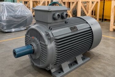
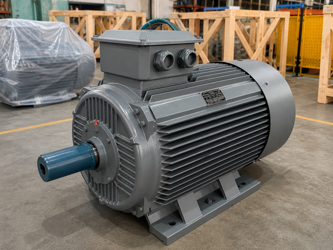
DRG Motor for Safe Braking Solutions
Dynamic braking, with a properly sized brake resistor and a correctly configured inverter, is the most common way to stop a motor safely and in a controlled manner. DRG AC asynchronous motors are produced compatible with inverter operation and dynamic braking applications. To set up the right braking solution in a crane, centrifuge, or high-inertia application, explore our DRG electric motor products; let us determine the most suitable motor and braking structure for your application together.