English
 Türkçe

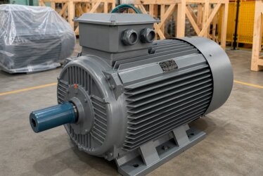
The rotation direction of an electric motor may look like a minor detail at first glance, but in many applications it is a critical matter that determines whether the job can be done correctly at all. A pump turning in the wrong direction cannot produce pressure, a fan running in reverse cannot blow air in the intended direction, and a conveyor running backward carries material to the opposite side. Moreover, in some applications the wrong rotation direction leads not only to inefficiency but directly to mechanical damage. In this article we examine how the rotation direction is determined and changed in three-phase and single-phase asynchronous motors, the forward-reverse control circuits, and the safety rules that must be followed when changing direction, drawing on DRG Motor's application experience.

Why does rotation direction matter?
Many mechanical systems are designed to work correctly in only one direction. Pumps, fans, compressors, conveyors and gearboxes are configured for a specific rotation direction. The wrong direction means low efficiency, performance loss and, in some cases, equipment damage. For this reason, verifying the rotation direction during commissioning is a fundamental step.
Although the rotation direction is thought of as a property of the motor, it is in fact a result of the relationship between the motor and its supply. The same motor can run in either direction when its connection is changed. Used correctly, this flexibility makes it easy to adapt to the application; managed wrongly, it leads to unexpected problems. For this reason, knowing how the rotation direction is determined and how it is changed should be basic knowledge for everyone who works with motors.
How does rotation direction arise in an asynchronous motor?
In a three-phase asynchronous motor, the rotation direction depends on the direction of the rotating magnetic field created in the stator. This rotating field turns clockwise or counterclockwise depending on the order in which the three phases are applied to the motor. Since the rotor follows this field, the motor's rotation direction is determined by the phase sequence. To examine the basic working principle of the motor, see our article on what an electric motor is.
The role of phase sequence
In a three-phase system, the phases are generally named L1, L2 and L3. The order in which these phases are applied to the motor determines the direction of the rotating field. When the phase sequence changes, the direction of the rotating field reverses and the motor begins to turn in the opposite direction. This is the fundamental logic of changing the rotation direction.
The concept of phase sequence is a fundamental feature of the three-phase system. The voltage of each phase reaches its peak value with a certain time difference relative to the others. This sequential rise creates a continuously rotating magnetic field in the stator. The order in which the phases arrive directly determines which way this field turns. For this reason, the rotation direction depends not so much on the motor's own construction as on the phase sequence of the supply applied to it. The same motor, when supplied with a different phase sequence, turns in the opposite direction without any mechanical change.
Swapping two of the three phases
The best-known way to change the rotation direction of a three-phase motor is to swap any two of the three phases. For example, swapping the connection of the L1 and L2 phases reverses the direction of the rotating field and the motor turns in reverse. Swapping all three phases, however, creates no change; the direction stays the same. Therefore, to change direction, only two phases are ever swapped.
Rotation direction at the terminal box
Changing the rotation direction is done in practice at the motor's terminal box or on the supply side. The structure of the terminal connections and the star-delta arrangement affect how this is done. Correctly understanding the terminal and star-delta connection structure is a prerequisite for changing direction without error.
How is the rotation direction checked?
A motor's rotation direction is defined according to whether it turns clockwise or counterclockwise when viewed from the shaft end. During commissioning, the motor is run briefly and the direction is observed. If the direction is wrong, two phases are swapped and the test is repeated. In equipment such as pumps where wrong-direction rotation is harmful, this check should be performed before the equipment is connected.
Direction check in pump applications
Centrifugal pumps produce the designed pressure and flow only when turning in the correct direction. A pump turning in reverse may pump a small amount of water; even though it appears to be working, it is actually inefficient and faulty. For this reason, the rotation direction is always verified when a pump is commissioned. In some pumps, reverse rotation can even cause the shaft nut to loosen.
Fan and blower applications
Fans, depending on their blade geometry, produce efficient airflow in only one direction. A fan turning in reverse provides very little air movement and wastes energy. In ventilation and cooling systems, direction control is mandatory for the system to deliver its designed performance.

What is forward-reverse (reversing) control?
In some applications the motor must run in both directions. Conveyors, cranes, doors and some processing machines move forward and backward. In this case, the rotation direction must be changed automatically through a control circuit rather than manually. This function is provided by the forward-reverse control circuit.
Two-contactor reversing circuit
The forward-reverse control circuit contains two separate contactors: one runs the motor in the forward direction, the other in the reverse direction. The reverse contactor is wired to cross-connect two phases; thus, when it engages, the phase sequence changes and the motor turns in reverse. When the forward contactor is energized, the motor turns one way; when the reverse contactor is energized, it turns the other way.
The correct operation of this circuit depends on the correct selection of the contactors and protection elements. Both contactors must have the capacity to handle the motor's rated current and frequent switching conditions. Since the contactors work more frequently than usual in reversing applications, it is appropriate to choose them slightly oversized in terms of contact life and heating. The principles of panel and contactor selection should be considered to design the circuit correctly. The thermal relay is placed on the common supply line so as to protect the motor in both directions.
Electrical interlock
If the forward and reverse contactors engage at the same time, it causes a direct short circuit between two phases. To prevent this, an electrical interlock is used: while one contactor is engaged, the coil circuit of the other is kept open. This interlock is mandatory for both safety and equipment protection. A mechanical interlock is also added, doubling the protection.
The electrical interlock is established by connecting the normally closed auxiliary contact of each contactor in series with the coil circuit of the other contactor. Thus, when the forward contactor is energized, the coil path of the reverse contactor is interrupted, and vice versa. The mechanical interlock is provided by a device through which the contactors physically block each other; while one contactor is engaged, the other is mechanically prevented from engaging. Using the two interlocks together provides redundancy against the possibility of a single protection layer failing. This is an indispensable safety measure, especially in high-power reversing applications.
Stopping time during direction change
To take a motor from forward to reverse, it must first be allowed to come to a complete stop. Suddenly reversing a rotating motor imposes very high stress on both the motor and the mechanical system. In the control circuit, a short delay is provided before the direction change so that the motor can stop. This is a protective practice for the motor and the load.
When a rotating motor is forced into reverse, the current drawn can be even higher than the normal starting current, because the motor first tries to stop its rotation and then accelerate in the opposite direction. This high current both overheats the winding and creates sudden shock loads on mechanical connections such as the shaft, coupling and gears. For this reason, a time-delay relay placed in the control circuit gives the reverse command only after waiting for the motor to stop safely. In systems with high load inertia, this waiting time becomes even more important.
Direction change and starting current
Every direction change means the motor starts again, which produces a high starting current. In applications that change direction frequently, this both stresses the grid and heats the motor. For this reason, using a frequency inverter is advantageous in systems that change direction very often.
Changing direction in single-phase motors
In single-phase asynchronous motors, the rotation direction is not as simple as in three-phase motors, because there is no phase sequence available; there is only a single phase. In these motors, the rotation direction is determined by the connection direction of the auxiliary winding relative to the main winding. To change direction, the leads of the auxiliary winding are swapped.
Auxiliary winding and capacitor
In single-phase motors, starting and direction are provided by the auxiliary winding and the capacitor. Changing the connection direction of the auxiliary winding reverses the direction of the rotating field. This operation is the single-phase counterpart of the phase swap in a three-phase motor. However, not every single-phase motor is suitable for changing direction; the motor's terminal structure must allow it.
In a single-phase motor, the phase difference created between the main winding and the auxiliary winding determines which way the motor will start. The capacitor is the element that creates this phase difference. Swapping the leads of the auxiliary winding reverses the direction of this phase difference and the motor starts in the other direction. If the auxiliary winding leads are accessible at the terminal box, this operation can be done; otherwise, it is not possible to change direction in motors whose factory connection is fixed. For this reason, in single-phase applications that must run in two directions, a motor with a terminal structure suitable for changing direction should be selected.
Direction control with a frequency inverter
When a frequency inverter is used, there is no need to change wiring to reverse the rotation direction. The drive can run the motor in reverse by electronically changing the phase sequence with a single command. This provides great convenience in applications requiring frequent direction changes. The frequency inverter also softens the direction change, reducing mechanical stress.

The relationship between phase sequence and phase loss
Since the rotation direction is directly related to the phase sequence, problems with the phases also affect direction behavior. The loss of one phase causes the motor to fail to start or to run under strain. In the case of phase loss, the motor cannot create a proper rotating field; therefore, phase protection is also the safeguard of direction control.
Using a phase-sequence relay
In critical applications, a phase-sequence relay is used to guarantee the correct phase sequence. This relay checks whether the phases are in the correct order and does not run the motor if they are in the wrong order. Especially in portable equipment or systems connected to different sockets, it prevents reverse rotation caused by a wrong phase sequence.
Grounding and safety
Every intervention made at the terminal box must be carried out in compliance with electrical safety rules. Power must always be cut before the operation, and the motor body must be properly grounded. While working with phase connections, a wrong contact can harm both the equipment and the worker.
Safety rules during commissioning
When checking the rotation direction, the motor must be run briefly and in a controlled manner. During this, one must stay away from rotating parts, the protective covers must be in place and the emergency stop must be accessible. Short test durations are preferred to avoid dry running in pumps and to ensure blade safety in fans.
If there is a coupling or pulley fitted to the motor's shaft end during the direction test, the risk of these rotating parts being thrown off must be taken into account. If possible, the test is done without load before the equipment is connected; this way the equipment is not damaged until the direction is verified. After the test, power is cut again and the permanent connection is made. This sequential approach protects both worker safety and equipment integrity. Commissioning operations must always be carried out by an authorized and competent person.
Forward-reverse in conveyor applications
In conveyor systems, material may need to be carried in two directions. When making a conveyor belt motor selection, whether the system will run forward and backward must be determined from the outset and the control circuit designed accordingly.
Crane and lifting applications
In cranes, raising and lowering a load require the motor to run in both directions. Crane and lifting motors, together with forward-reverse control, also need a brake structure for safe stopping. Here, direction control and braking are designed together.
Voltage unbalance and direction behavior
Voltage unbalance between phases can disrupt the smoothness of the rotating field and affect the motor's torque. Even if the direction is correct, an unbalanced supply prevents the motor from turning smoothly and efficiently. The effect of voltage unbalance shows that supply quality is as important as direction control. For healthy rotation, both the phase sequence and the phase voltages are expected to be balanced.
Direction control in industrial applications
In general, in installations using industrial electric motors, the correct rotation direction affects both production quality and equipment life. The correct rotation of the many motors on a production line is the foundation of the system's harmonious operation.
Common mistakes when changing direction
The most common mistake is swapping all three phases and being surprised that the direction does not change; in fact, only two phases should be swapped. Other mistakes are skipping the interlock, reversing the motor before it stops, and intervening at the terminals without cutting power. Each of these mistakes can lead to equipment damage or danger.
The returns of correct direction control
A correctly established direction control and, where needed, a safe forward-reverse control circuit ensure that the equipment operates at its designed performance, that mechanical stresses are reduced and that operating safety is increased. This seemingly simple topic is in fact one of the cornerstones of a healthy drive system.
DRG Motor for the right drive solutions
DRG Motor evaluates its asynchronous motors in line with the direction and control requirements of the application. DRG Motor offers engineering support for systems that must run forward and backward, for the correct terminal structure and for drive-compatible motor selection. To determine together the motor and control solution best suited to your application, get in touch with the DRG Motor team.