English
 Türkçe

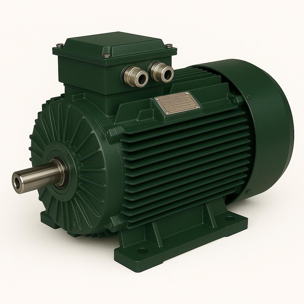
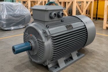
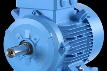
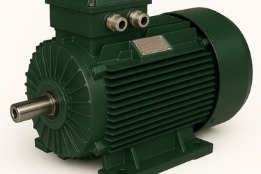
When you look at the nameplate of an electric motor, you encounter many markings such as the insulation class, the protection class, and the efficiency class. Among them there is a code that is often overlooked but says a great deal about the motor's thermal safety: the TP code, that is, the thermal protection class. The TP marking describes in a standard language how and to what extent the motor is protected against overheating. To select DRG AC asynchronous motors correctly and operate them safely, it is important to be able to read this code. In this article we cover what the TP code means, what its digits express, and its relationship with embedded thermal protection.

What Is the TP Code?
The TP code is an abbreviation of the words "Thermal Protection" and indicates the type and degree of protection a motor provides against overheating conditions. This marking is based on the international standard IEC 60034-11 and is expressed with the digits that follow the letters "TP." The code summarizes under which type of overload conditions, in how many stages, and at which temperature level the motor is protected.
Why Is It Important?
The greatest enemy of a motor is excessive temperature. When the winding temperature exceeds the endurance limit of the insulation, the insulation ages rapidly and the motor's life shortens. The TP code clearly states what kind of protection the motor contains against this overheating; this makes it possible to select the protection level suitable for the application.
The IEC 60034-11 Standard
The TP marking is defined within the framework of the IEC 60034-11 standard, which describes the thermal protection of motors. This standard places into a systematic code structure which overload type the protection covers, how many stages it consists of, and the permitted temperature level. Thanks to the standard, motors from different manufacturers can be compared in the same language.
The Structure of the TP Code
The TP code consists of a group of usually three digits following the letters "TP." Each of these digits carries different information: the first digit shows which overload type the protection covers, the second digit shows the number of protection stages, and the third digit shows the permitted temperature level. The table below summarizes this structure.
| Position | Meaning | Value | Explanation |
|---|---|---|---|
| 1st Digit | Overload type | 1 | Protection only against slowly varying (continuous) overload |
| 2 | Protection against both slowly varying and fast (such as locked rotor) overload | ||
| 2nd Digit | Protection stage | 1 | Single-stage protection (trip only) |
| 2 | Two-stage protection (first warning, then trip) | ||
| 3rd Digit | Permitted temperature level | 1 | Lower temperature threshold (most protective level) |
| 2 | Medium temperature threshold | ||
| 3 | Higher temperature threshold |
As can be seen from this table, for example the marking "TP 211" describes a motor that provides protection against both slow and fast overload, with a single stage, and at a low temperature threshold. When each digit of the code is read, the motor's protection behavior is clearly understood.
First Digit: Overload Type
The first digit shows which type of overload the protection covers. The value "1" expresses protection only against slowly developing overloads, that is, ones that occur over a long time (for example continuous overload or poor cooling). The value "2" additionally covers fast-developing overloads as well; the most typical example of this is a locked rotor, in which case the temperature shoots up to a dangerous level within seconds.

Second Digit: Protection Stage
The second digit specifies how many stages the protection has. Single-stage protection directly disconnects the motor when the temperature reaches the threshold. Two-stage protection first gives a warning signal; this allows the operator to take a measure such as reducing the load, and if the temperature continues to rise, the second stage stops the motor. Two-stage protection reduces unplanned stops in processes where continuous operation is critical.
Third Digit: Temperature Level
The third digit shows at which temperature threshold the protection will engage. A low value means the protection engages earlier (at a lower temperature); this is the most protective option. A high value allows operation up to a higher temperature. The temperature threshold must be selected compatible with the motor's insulation class; otherwise the protection either trips too early and disrupts production or acts too late and puts the insulation at risk.
Relationship with the Insulation Class
The temperature thresholds in the TP code are directly linked to the motor's insulation class. The insulation class defines the maximum temperature the winding can safely withstand; the thermal protection prevents the winding from reaching this limit. When the two are read together, the motor's thermal safety is fully understood. To see the insulation classes in detail, see our article on electric motor insulation class.
Embedded Thermal Protection
For the TP marking to be provided, there are thermal sensors placed inside the motor, usually at the hottest points of the winding. Because these embedded sensors measure the winding temperature directly, they provide much more realistic protection than protections that measure current from the outside. Since the sensor sees the real temperature of the winding, it can also catch sudden and local heating.
Relationship with PTC and Bimetal
Embedded thermal protection is usually provided with a PTC thermistor or a bimetal contact. The PTC thermistor abruptly increases its resistance at a certain temperature, triggering a protection relay. The bimetal contact, on the other hand, bends with temperature and opens the circuit directly. To see the operating logic and differences of these elements in depth, we recommend our article on motor thermistor PTC and PT100 protection.
PTC or Bimetal?
Bimetal contacts are simple and economical; they cut the current directly but have a relatively slow response time. PTC thermistors respond faster and more sensitively but must be used with a protection relay. Against fast-developing overloads (that is, protections where the second digit of TP is "2"), PTC solutions are more suitable. The choice is made according to the application's overload profile.
Reading It on the Nameplate
The TP code appears on the motor's nameplate together with other markings. Finding the letters "TP" and the group of digits that follow on the label lets you instantly learn the motor's thermal protection behavior. If there is no TP marking on the label, it may mean that the motor does not have embedded thermal protection or that protection is provided by a separate circuit; in that case it is wise to consult the manufacturer.
Connection with Temperature Rise
To understand when the TP protection will engage, it is necessary to know the motor's temperature rise during normal operation. Temperature rise shows how much hotter the motor gets than the environment while running under load. If this value is within normal limits, the protection is not triggered unnecessarily. To see the topic in detail, our article on motor temperature rise is helpful.

The Importance of TP in Inverter Operation
Motors driven by a frequency inverter heat up more easily, especially at low speeds, because the cooling fan slows down. In addition, inverter-induced harmonics generate extra heat. For this reason, embedded thermal protection becomes even more critical in motors operating with an inverter, because a protection that measures current from the outside may not fully see the heating at low speed.
The Difference from Overcurrent Protection
A motor protection switch or thermal relay measures the current the motor draws and cuts the circuit at overcurrent. However, this protection does not see the motor's real temperature; for example, even if the motor overheats due to a blocked cooling channel, the current may remain normal. The advantage of TP protection is that it measures the temperature directly at its source, that is, at the winding.
Single Stage and Two Stage in Practice
Single-stage protection is simple and clear: the temperature reaches the threshold, the motor stops. This approach is sufficient in applications where stopping is not costly. Two-stage protection gains value where the continuity of production is important. When the first stage gives a warning, the operator or automation system can reduce the load, control the cooling, or plan a controlled stop. This prevents sudden and unplanned stops; the second stage engages only as a last safety measure.
The Effect of Ambient Temperature
A motor's heating depends not only on the load but also on the temperature of the environment in which it operates. A motor working in a hot boiler room or under the sun reaches a higher winding temperature at the same load. In this case the TP protection engages and keeps the motor safe; however, in correct motor selection the ambient temperature must be taken into account from the start. Otherwise the protection is triggered constantly and production is disrupted. For this reason, in places with high ambient temperature, both an appropriate insulation class and an appropriate TP level are evaluated together.
Frequent Start-Stop and Heat Build-Up
In motors that start frequently, the high current drawn at each start heats the winding. If there is not enough time for cooling between starts, heat accumulates over time and the winding temperature can rise to a dangerous level. In such applications, embedded thermal protection directly catches this gradual heat build-up that current-measuring protections may miss. Therefore, TP protection is especially valuable in applications with a frequent start-stop profile.
Catching Cooling Deficiency
Blockage of the motor's fan cover, the cooling fins becoming covered with dust, or fan failure overheats the motor even if the current remains normal. Such mechanical cooling problems cannot be noticed by a protection that only measures current. The embedded TP sensor, on the other hand, catches this situation immediately because it sees the real temperature of the winding and protects the motor. This is one of the most important practical advantages of TP protection. In practice, many motor failures stem from cooling problems that go unnoticed because the current looks normal; embedded protection makes this silent danger visible.
The Location Where the Sensor Is Placed
The effectiveness of embedded thermal protectors depends on their location within the winding. The sensors are usually placed at the points anticipated as the hottest region of the winding, one per phase. This way the temperature of the most critical region is represented. A misplaced sensor reduces the value of the protection, as it may notice the real hot spot late. For this reason, sensor placement is carefully planned during production.
Protection Relay and System Integrity
A PTC-based TP protection does not work on its own; it needs a protection relay that reads the resistance change of the sensor and stops the motor. This relay also monitors the continuity of the sensors, staying on the safe side even in the event of a cable break. Therefore, TP protection is a chain: the embedded sensor, the connection cables, and the protection relay work together. If any link in the chain is missing, the protection does not take place.
Automatic and Manual Reset
When a TP protection is triggered, how the motor returns to operation is also important. Some protections automatically reset by returning to operation on their own once the winding cools; this is practical in places where human intervention is difficult but can hide repeated triggerings. Manual reset, on the other hand, requires the operator to notice and confirm the situation; this ensures the fault is not overlooked. In safety-critical applications, manual reset is preferred, because each triggering should be evaluated as a warning.
Which TP Level Is Needed?
The right TP level depends on the application. In an application running at a continuous and constant load with a low risk of sudden locking, protection with a first digit of "1" may be sufficient. In applications with a risk of frequent blockage, sudden locking, or variable load, protection with a first digit of "2", sensitive also to fast overload, should be preferred. In critical processes, two-stage protection (second digit "2") reduces unplanned stops.
Common Misunderstandings
The TP code is often confused with the protection class (IP); however, IP describes protection against dust and water, while TP describes thermal protection. The two are completely different concepts. Another mistake is to think that every motor with a TP marking is protected against every type of overload; however, the overload type covered is limited by the first digit. Reading the code digit by digit prevents these misconceptions.
Caution in Selection and Maintenance
When selecting a motor, the TP code should be evaluated according to the application's overload and temperature profile. During commissioning, it should be ensured that the embedded sensor is connected correctly to the protection relay, and during periodic maintenance, it should be tested that this protection chain works. A TP sensor whose protection circuit is not connected is useless, even if it is written on the label.
Testing During Commissioning
When a motor is commissioned for the first time, it should be tested whether the TP protection chain actually works. This test verifies that the sensor terminals are connected correctly to the protection relay and that the motor actually stops when the relay is triggered. Many faults grow years later, when protection is needed, because of a disabled protection chain; whereas a simple test during commissioning eliminates this risk. For this reason, a function test of the TP protection should be part of the acceptance procedure.
Tracking TP Information in Documents
The TP level is clearly stated in the motor's technical documents and test reports. Easy access of maintenance teams to this information ensures the protection structure is correctly understood in future interventions. Especially in facilities with a large number of motors, keeping a record of each motor's TP level also facilitates spare part and protection relay planning. This small discipline noticeably improves fault management in the long run.
TP in Industrial Applications
In heavy industrial applications, in pumps, fans, and conveyors, motors operate under variable and demanding conditions. In these applications, the right TP level significantly reduces unexpected motor failures and the associated production losses. To examine our wide range of motors, take a look at our article on industrial electric motors.
DRG Motor for Safe Thermal Protection
The TP code is valuable information that describes in a standard language how much and how a motor is protected against overheating. Reading this code correctly is the key to selecting the protection suitable for the application and extending the motor's life. DRG AC asynchronous motors are produced for safe operation with embedded thermal protection options and correct TP marking. To determine the thermal protection level suitable for your application, explore our DRG electric motor products; let us select the most suitable protected motor for your needs together.