English
 Türkçe

The correct operation of an electric motor depends not only on its power, speed and efficiency, but also on how it is mounted. The way the motor connects to the machine, that is the mounting type, forms the basis of mechanical fit, vibration behaviour and long service life. The mounting types most often encountered in industry are B3 (foot-mounted), B5 (large flange), B14 (small flange) and B35 (foot + flange combined). In this article we compare these four basic mounting types, the IM codes in the IEC 60034-7 standard, and which should be preferred in which application. For basic motor concepts, our article on what is an electric motor is a good starting point.

Why Does Mounting Type Matter?
The motor's mounting type determines not only how the motor is physically fixed, but also the shaft direction, the manner of load transfer and the mechanical integration with the machine. A wrong mounting-type choice can lead to alignment problems, excessive vibration, shortened bearing life and even motor failure. The right mounting type, by contrast, both eases installation and ensures the motor runs trouble-free throughout its expected life. So in motor selection the mounting type must be determined as carefully as the power and speed.
IEC 60034-7 and IM Codes
The mounting types of electric motors are defined by the international standard IEC 60034-7. In this standard each mounting arrangement is expressed by an "IM" (International Mounting) code. The commonly used short codes such as B3, B5 and B14 are in fact the practical equivalents of these IM codes. For example B3 corresponds to IM B3 (IM 1001), and B5 corresponds to IM B5 (IM 3001). IM codes precisely define whether the motor is foot- or flange-mounted, whether the shaft is horizontal or vertical, and the shaft direction.
Mounting Types Comparison Table
The table below compares the four basic mounting types in terms of structure, connection method and typical use. It helps you quickly determine the right mounting type.
| Mounting Type | Structure / Mounting | Connection | Typical Use |
|---|---|---|---|
| B3 | Foot-mounted (feet under the frame) | Bolted to floor/base via feet | Belt-pulley, general industry, pump |
| B5 | Large flange (clearance holes, FF type) | Front flange bolts (clearance holes) | Pump, gearbox, reducer |
| B14 | Small flange (tapped, FT type) | Tapped holes on the front flange | Small pump, compact machines |
| B35 | Foot + flange (combined) | Both foot and flange connection | Heavy reducer, high torque, secure fit |
B3 Foot Mounting
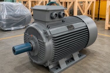
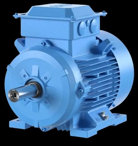
B3 is the most common and best-known mounting type. There are feet under the motor frame, and the motor is fixed by bolts through these feet to a floor, base or foundation. The shaft is horizontal. B3 mounting is ideal especially in belt-pulley drives, in applications where the motor sits on a base separate from the machine. It is easy to install, alignment can be checked visually, and the motor can easily be removed and replaced when needed. The bulk of general industrial drives are done with B3 foot-mounted motors. This type is used in most three-phase motor in industry applications.
B5 Large Flange Mounting
In B5 mounting there is a large connection flange at the front of the motor, around the shaft. Through clearance holes on this flange (FF-type flange), the motor is bolted directly to a pump, reducer or gearbox. The motor has no feet; the entire load is carried by the flange. B5 is used in applications where the motor is joined directly and axially to the driven machine. This usually removes the need for a separate coupling alignment process, because the flange connection ensures axial alignment by itself. It is the most preferred mounting type for pump and reducer connections.

B14 Small Flange Mounting
B14, like B5, is a flange mounting, but its flange is smaller and of a different type. Instead of clearance holes, the B14 flange has tapped holes (FT-type flange); that is, the bolts thread into tapped holes on the motor's front face. This compact structure is preferred on low-power motors and on machines where saving space matters. B14 is ideal for small pumps, compact machine units and tight mounting spaces. The small flange keeps the connection light and compact.
B35 Combined (Foot + Flange) Mounting
B35 is the combination of B3 and B5: the motor has both feet and a large connection flange. This way the motor can be fixed to the floor by its feet and also connected to the driven machine by its flange. This dual connection provides extra mechanical safety and rigidity, especially in reducer applications carrying high torque and heavy loads. B35 is preferred in heavy applications with high vibration and mechanical stress, both to guarantee alignment and to carry the load at two points. It is the most rigid but least flexible mounting type.
The Difference Between FF and FT Flanges
In flange mountings there are two basic flange types: FF and FT. The FF (clearance-hole) flange is used in B5; it has plain, untapped holes, and bolts pass through these holes to fasten to the counter machine. The FT (tapped-hole) flange is used in B14; the holes are tapped and the bolts thread directly into them. This difference determines which side carries the thread and how the connection is made. A wrong flange-type choice can mean the motor cannot connect to the machine at all; so the flange type must always be verified before ordering.
Horizontal and Vertical Mounting
Mounting types are not limited to the foot/flange distinction; the shaft direction also matters. B3, B5 and B35 are usually used for horizontal-shaft mounting. But many motors can also be mounted vertically, with the shaft pointing up or down; in that case the V-series IM codes (for example V1, V3) come into play. Vertical mounting is required in submersible pumps, vertical mixers and some fan applications. In vertical mounting, bearing selection and lubrication must be handled specially to carry the axial load.

Which Application Calls for B3?
B3 foot mounting is the first choice in belt-pulley-driven systems, in installations where the motor sits on a base independent of the machine, and in general-purpose industrial drives. Conveyors, fans, compressors and many pump applications are solved with B3. B3 is also advantageous where the motor must be easily removed and replaced. The majority of the world of industrial electric motors runs on foot mounting.
Which Application Calls for B5 or B14?
B5 and B14 flange mountings are preferred in applications where the motor is connected directly and axially to a machine (pump, reducer). B5 is used at larger powers and heavier connections; B14 at small powers and on compact machines. Flange mounting eliminates the need for a separate coupling alignment, speeding up installation and guaranteeing axial alignment. In pump sets and monobloc applications, flange-mounted motors are standard.
Which Application Calls for B35?
B35 combined mounting is preferred in applications involving high torque, heavy load and high vibration. B35 is ideal especially in systems where heavy reducers are directly driven and both a flange connection and foot support are needed. The dual connection increases safety by supporting the motor mechanically at two points. For lifting and crane applications requiring high starting torque, our article on crane and lifting electric motors offers complementary information.
The Structure and Reading of IM Codes
The IEC 60034-7 standard offers two coding systems: Code I (for example IM B3, IM B5) and Code II (for example IM 1001, IM 3001). Code I is the traditional letter-number combination common in everyday use; Code II is a fully numeric, more detailed system. In Code II the first digits define the general mounting arrangement, while the following digits define the shaft direction and special cases. For most users Code I is sufficient; but in international projects or where special mounting is required, it is useful to know the exact Code II equivalent. Including both codes on the nameplate and in the catalogue prevents misunderstanding of the motor's mounting arrangement. Thanks to this standard approach, the motors of different manufacturers are described in the same language, ensuring interchangeability.
The Relationship Between Mounting Type and Frame Size
The motor's mounting type must be evaluated together with the frame size. A motor of the same power can be offered in different mounting types; however, the flange dimensions and foot-hole spacings are set by standards. Thanks to these standard dimensions, it is easy to replace a motor with another of the same mounting type. For example, since the bolt-circle diameter and spigot dimension of a B5 flange at a given frame size are standardised, motors of the same size from different brands can be fitted in place of one another. This interchangeability is an important advantage that greatly eases spare-parts management and plant maintenance. To choose the right frame size and mounting type combination, our article on mounting type selection is helpful.
How to Identify Mounting Type From the Nameplate
A motor's mounting type is usually stated on its nameplate as an IM code. You will see an expression such as "IM B3", "IM B5" or "IM B35" on the nameplate. This code precisely defines how the motor should be mounted. Stating this code correctly when ordering a spare part or a new motor prevents the wrong motor from arriving. To read nameplate information correctly, our article on electric motor nameplate information is a good resource.
The Effect of Mounting Type on Cooling
The mounting type can also affect the motor's cooling performance. Most standard motors self-cool with a fan at the shaft end and shed heat through fins on the frame. On motors mounted vertically with the fan cover pointing up, an additional rain cover is used to prevent rain and foreign objects entering the fan grille. The surface on which the motor is mounted can also carry away some heat by conduction; in flange mounting, when the motor is connected directly to a metal body, this conduction contributes to cooling. In cramped or enclosed mounting spaces, it is important not to restrict the airflow so the motor does not overheat; where necessary, external cooling or a higher protection class should be chosen.
The Balance of Axial and Radial Loads
The mounting-type choice must be evaluated together with the axial and radial loads on the motor shaft. In belt-pulley drives a side (radial) load acts on the shaft; in that case foot-mounted B3 and a suitable bearing choice are important to carry the side load safely. In directly coupled applications such as pumps, the axial load may dominate; flange mounting and bearings suited to the axial load are preferred. Wrong load estimation leads to early bearing wear and shaft bending. So the mounting type must be chosen with an engineering eye, together with the load type.
Mounting Type and Ease of Maintenance
A motor's ease of maintenance and replacement is closely related to the mounting type. B3 foot-mounted motors are usually easy to remove and refit; when the foot bolts are released, the motor can be lifted out. In flange-mounted motors, since the motor is connected directly to the machine, the removal process must be planned more carefully depending on the machine's structure. In B35 combined mounting, since both the foot and the flange connection must be released, maintenance can take a little longer; but this is a natural trade-off for the mechanical safety it provides. This ease-of-maintenance dimension should also be considered in plant planning.
The Relationship Between Soft Starting and Mounting
The motor's mounting type also affects the mechanical stress during starting. In a motor that comes on with high starting torque, the mounting connection must be rigid enough to safely withstand this sudden torque; otherwise the foot bolts can loosen or the flange connection can be stressed. B35 combined mounting is preferred in high-starting-torque applications for exactly this reason. To reduce the starting shock, the methods in our articles on soft-starting advantages and energy savings with a frequency inverter protect both the mounting connection and the mechanical transmission components. Thus the right mounting type together with the right starting method extends the life of the motor and the connected equipment.
Alignment and Vibration
The mounting type directly affects alignment quality and therefore the vibration level. Since flange mountings (B5, B14) ensure axial alignment by themselves, they reduce the risk of coupling alignment error. In foot mounting (B3), alignment must be done carefully; a poorly aligned belt-pulley or coupling leads to vibration and early bearing failure. The right mounting-type choice and careful installation are the key to a quiet, long-lived motor.
Common Mistakes in Mounting Type Selection
The most common mistake is confusing the flange type (FF/FT, B5/B14); a large-flange motor cannot be fitted to a small-flange machine. The second mistake is using a horizontal-mounting motor in an application that requires vertical mounting; this leads to the bearings being unable to carry the axial load. The third is assuming that the flange connection alone will be sufficient in heavy, vibration-prone applications; in such cases B35 combined mounting is safer. For the right kW and speed selection, see our article on high and low kW motors.
Choosing the Right Mounting Type With DRG Motor
In an electric motor, the mounting type is a critical decision that determines the motor's fit with the machine, its vibration behaviour and its lifespan. B3 foot mounting, B5 and B14 flange mounting, or B35 combined mounting; each answers a different application need. Choosing the right mounting type both eases installation and ensures your motor runs trouble-free for years. At DRG Motor we offer motors in all standard mounting types, including B3, B5, B14 and B35, in the frame size and power suited to your application. To determine the right mounting type together, you can review the DRG Motor products and get technical support from our expert team, or visit our homepage.